What are the Types of Cable
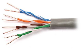
- Twisted Pair - A twisted pair cable is a type of cable made by putting two separate insulated wires together in a twisted pattern and running them parallel to each other. This type of cable is widely used in different kinds of data and voice infrastructures.Experts point out that twisted pair cabling is often used to help avoid certain kinds of signal interference. Two different types of twisted pair cable, unshielded twisted pair (UTP) and shielded twisted pair (STP) are used in different kinds of installations. UTP is common in Ethernet installations, while STP is used in various kinds of networks to prevent cross talk and electromagnetic interference. STP cable can also help to provide grounding.
 In general, twisted-pair cabling may be preferred over a common alternative, coaxial cable, for different reasons. Coaxial cable involves a single, thicker wire. Many of those who use this type of cable claim that twisted pair has a more accommodating bend radius, is easier to terminate, and provides more versatility in selecting network topologies. Different kinds of twisted-pair cable are rated by industry standards including ISO/EIC and EIA/TIA.


STP ADVANTAGES
Through the use of the a metallic foil, it is possible to cancel out the electromagnetic interference thoroughly to maintain faster data transfer speeds. For companies that need that security it is important to make sure that your network cabling is all STP standard otherwise there is the possibility of either throttled data speeds or even outages.
STP DISADVANTAGES
However, like everything if there are advantages, there are also disadvantages and in this case there are number of disadvantages:
- Cost - the STP cables are noticeably more expensive in cost which can add up quickly.
- Size - due to the foil in casing the cable size increases that's more space is needed when cabling your network.
- Installation - a higher level of expertise is needed when installing the cables as the STP cables need to be grounded. if they are not grounded then the shield doesn't work and data transfer speed suffer or outages may occur.
- Fragile - If the foil is compromised anywhere along the cable, the shielding is then rendered useless.
b. UTP (Unshielded Twisted Pair)- A pair of unshielded wires wound around each other is known as Unshielded Twisted Pair Cables (UTP).
 An UTP is a pair of copper wires would by plastic insulators. Unshielded Twisted Pair Cables (UTP) is the cheapest form of cables available for networking purposes. It is highly used in Local Area Network (LAN) environments. The installation cost of the cable is very cheap as it is easy to install.
UNSHIELDED ADVANTAGES
Mainly what are considered the disadvantages of the Shielded are the advantages of the unshielded.
For most networks, whether they be home or in an office, unshielded should be fit for purpose. They cancel out interference by being twisted, just as the shielded but at a way more precise level. So their advantages are:
- Cost - cheaper than the STP.
- Maintenance - As there is no foil to break and bo? grounding cable, there is less to break. This reduces the need to find a small tear in the foil.
- Installation - No need for extra special care to be taken of the cables during installation.
- Size - smaller and less sensitive makes it easier to squeeze them into tight spaces.
- Ubiquity - Use in most situations so there are more common.
UNSHIELDED DISADVANTAGES
Really the only disadvantage that UTP have over STP is when they would be used in an environment not fit for purpose. Meaning that they would be used in a situation where there is a lot of electromagnetic noise.
To Sum up, if there is a lot of electromagnetic noise that needs to be cancelled, then go with the STP cables, otherwise the UTP cables should suit your needs just fine.
2. Coaxial- Coaxial cable is a type of copper cable

Coaxial cable received its name because it includes one physical channel that carries the signal surrounded -- after a layer of insulation -- by another concentric physical channel, both running along the same axis. The outer channel serves as a ground. Many of these cables or pairs of coaxial tubes can be placed in a single outer sheathing and, with repeaters, can carry information for a great distance.
Coaxial cable was invented in 1880 by English engineer and mathematician Oliver Heaviside, who patented the invention and design that same year. AT&T established its first cross-continental coaxial transmission system in 1940. Depending on the carrier technology used and other factors, twisted pair copper wire and optical fiber are alternatives to coaxial cable.
How coaxial cables work
Coax cables have concentric layers of electrical conductors and insulating material. This construction ensures signals are enclosed within the cable and prevents electrical noise from interfering with the signal.

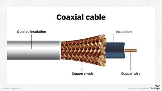
The center conductor layer is a thin conducting wire, either solid or braided copper. A dielectric layer, made up of an insulating material with very well-defined electrical characteristics, surrounds the wire. A shield layer then surrounds the dielectric layer with metal foil or braided copper mesh. The whole assembly is wrapped in an insulating jacket. The outer metal shield layer of the coax cable is typically grounded in the connectors at both ends to shield the signals and as a place for stray interference signals to dissipate.
A key to coaxial cable design is tight control of cable dimensions and materials. Together, they ensure the characteristic impedance of the cable takes on a fixed value. High-frequency signals are partially reflected at impedance mismatches, causing errors.
Characteristic impedance is sensitive to signal frequency. Above 1 GHz, the cable maker must use a dielectric that doesn't attenuate the signal too much, or change the characteristic impedance in a way that creates signal reflections.
Electrical characteristics of coax are application-dependent and crucial for good performance. Two standard characteristic impedances are 50 ohm, used in moderate power environments, and 75 ohm, common for connections to antennas and residential installations.
Types of coaxial cables
Hard-line coaxial cable relies on round copper tubing and a combination of metals as a shield, such as aluminum or copper. These cables are commonly used to connect a transmitter to an antenna. Triaxial cable has a third layer of shielding that is grounded to protect signals transmitted down the cable. Rigid-line coaxial cables are made up of twin copper tubes that function as unbendable pipes. These lines are designed for indoor use between high-power radio frequency (RF) transmitters. Radiating cable mimics many components of hard-line cable, but with tuned slots in the shielding matched to the RF wavelength at which the cable will operate. It is commonly used in elevators, military equipment and underground tunnels.
Uses of coaxial cables
 In the home and small offices, short coaxial cables are used for cable television, home video equipment, amateur radio equipment and measuring devices. Historically, coaxial cables were also used as an early form of Ethernet, supporting speeds of up to 10 Mbps, but coax has supplanted by the use of twisted pair cabling. However, they remain widely in use for cable broadband internet. Coaxial cables are also used in automobiles, aircraft, military and medical equipment, as well as to connect satellite dishes, radio and television antennae to their respective receivers.
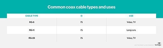
Standards
Most coaxial specifications have impedance of 50, 52, 75 or 93 ohm. Because of widespread use in the cable television industry, RG-6 cables with double or quad shields and impedance of 75 ohm have become a de facto standard for many industries. Nearly 50 distinct standards exist for coaxial cable, often designed for specific use cases in amateur radio or low-loss cable television. Other examples include RG-59/U used for carrying broadband signal from closed circuit TV systems or RG-214/U used for high-frequency signal transmission.
Connectors for coax range from simple single connectors used on cable TV systems to complicated combinations of multiple thin coax links, mixed with power and other signal connections, housed in semi-custom bodies. These are commonly found in military electronics and avionics.
Mechanical stiffness can vary tremendously, depending on the internal construction and intended use of the coaxial cabling. For example, high-power cables are often made with thick insulation and are very stiff.
Some cables are deliberately made with thick center wires, resulting in skin-effect resistance. It results from high-frequency signals traveling on the surface of the conductor, not throughout. If the center conductor is larger, it results in a stiff cable with low loss per meter.
Interference issues
Coaxial cables can experience a variety of different forms of interference. Signal leakage occurs when the electromagnetic field passes through the shielding on the outside of the cable. In other cases, outside signal can leak through the insulation. Straight-line feeds to commercial radio broadcast towers have the least leakage and interference, because these cables have smooth, conductive shields with few gaps in them. Interference is most significant in nuclear reactors, where special shielding is needed.
 3. Fiber Optic- Fiber optics, or optical fiber, refers to the medium and the technology associated with the transmission of information as light pulses along a glass or plastic strand or fiber. A fiber optic cable can contain a varying number of these glass fibers -- from a few up to a couple hundred. Surrounding the glass fiber core is another glass layer called cladding. A layer known as a buffer tube protects the cladding, and a jacket layer acts as the final protective layer for the individual strand.
How fiber optics works
 Fiber optics transmit data in the form of light particles -- or photons -- that pulse through a fiber optic cable. The glass fiber core and the cladding each have a different refractive index that bends incoming light at a certain angle. When light signals are sent through the fiber optic cable, they reflect off the core and cladding in a series of zig-zag bounces, adhering to a process called total internal reflection. The light signals do not travel at the speed of lightbecause of the denser glass layers, instead traveling about 30% slower than the speed of light. To renew, or boost, the signal throughout its journey, fiber optics transmission sometimes requires repeaters at distant intervals to regenerate the optical signal by converting it to an electrical signal, processing that electrical signal and retransmitting the optical signal.
Types of fiber optic cables
Multimode fiber and single-mode fiber are the two primary types of

DIFFERENCE BETWEEN STRAIGHT-THROUGH CABLE AND CROSSOVER
Ethernet cables can be wired as straight through or crossover. The straight through is the most common type and is used to connect computers to hubs or switches. They are most likely what you will find when you go to your local computer store and buy a patch cable. Crossover cable is more commonly used to connect a computer to a computer and may be a little harder to find since they aren’t used nearly as much as straight through cable. Then, what’s the difference between them? Difference between straight through and crossover cables will be introduced in this blog.
T568A And T568B Wiring Standard Basis
A RJ45 connector is a modular 8 position, 8 pin connector used for terminating Cat5e patch cable or Cat6 cable. A pinout is a specific arrangement of wires that dictate how the connector is terminated. There are two standards recognized by ANSI, TIA and EIA for wiring Ethernet cables. The first is the T568A wiring standard and the second is T568B. T568B has surpassed 568A and is seen as the default wiring scheme for twisted pair structured cabling. If you are unsure of which to use, choose 568B.
A RJ45 connector is a modular 8 position, 8 pin connector used for terminating Cat5e patch cable or Cat6 cable. A pinout is a specific arrangement of wires that dictate how the connector is terminated. There are two standards recognized by ANSI, TIA and EIA for wiring Ethernet cables. The first is the T568A wiring standard and the second is T568B. T568B has surpassed 568A and is seen as the default wiring scheme for twisted pair structured cabling. If you are unsure of which to use, choose 568B.

What Is Straight Through Cable?
A straight through cable is a type of twisted pair cable that is used in local area networks to connect a computer to a network hub such as a router. This type of cable is also sometimes called a patch cable and is an alternative to wireless connections where one or more computers access a router through a wireless signal. On a straight through cable, the wired pins match. Straight through cable use one wiring standard: both ends use T568A wiring standard or both ends use T568B wiring standard. The following figure shows a straight through cable of which both ends are wired as the T568B standard.
A straight through cable is a type of twisted pair cable that is used in local area networks to connect a computer to a network hub such as a router. This type of cable is also sometimes called a patch cable and is an alternative to wireless connections where one or more computers access a router through a wireless signal. On a straight through cable, the wired pins match. Straight through cable use one wiring standard: both ends use T568A wiring standard or both ends use T568B wiring standard. The following figure shows a straight through cable of which both ends are wired as the T568B standard.

What Is Crossover Cable?
An Ethernet crossover cable is a type of Ethernet cable used to connect computing devices together directly. Unlike straight through cable, crossover cables use two different wiring standards: one end uses the T568A wiring standard, and the other end uses the T568B wiring standard. The internal wiring of Ethernet crossover cables reverses the transmit and receive signals. It is most often used to connect two devices of the same type: e.g. two computers (via network interface controller) or two switches to each other.
An Ethernet crossover cable is a type of Ethernet cable used to connect computing devices together directly. Unlike straight through cable, crossover cables use two different wiring standards: one end uses the T568A wiring standard, and the other end uses the T568B wiring standard. The internal wiring of Ethernet crossover cables reverses the transmit and receive signals. It is most often used to connect two devices of the same type: e.g. two computers (via network interface controller) or two switches to each other.

Choose a Straight Through or Crossover Cable?
Usually, straight through cables are primarily used for connecting unlike devices. And crossover cables are use for connecting unlike devices alike devices.
Use straight through cable for the following cabling:
Usually, straight through cables are primarily used for connecting unlike devices. And crossover cables are use for connecting unlike devices alike devices.
Use straight through cable for the following cabling:
- Switch to router
- Switch to PC or server
- Hub to PC or server
Use crossover cables for the following cabling:
- Switch to switch
- Switch to hub
- Hub to hub
- Router to router
- Router Ethernet port to PC NIC
- PC to PC

Conclusion
Straight through and crossover cables are wired differently from each other. One easy way to tell what you have is to look at the order of the colored wires inside the RJ45 connector. If the order of the wires is the same on both ends, then you have a straight through cable. If not, then it’s most likely a crossover cable or was wired wrong. At present, the straight through cable is much more popular than crossover cable and is widely used by people. FS.COM provides a full range straight through Cat5e, Cat6, Cat6a and Cat7 Ethernet cables with many lengths and colors options. Look for Ethernet patch cables, just come to FS.COM!
Straight through and crossover cables are wired differently from each other. One easy way to tell what you have is to look at the order of the colored wires inside the RJ45 connector. If the order of the wires is the same on both ends, then you have a straight through cable. If not, then it’s most likely a crossover cable or was wired wrong. At present, the straight through cable is much more popular than crossover cable and is widely used by people. FS.COM provides a full range straight through Cat5e, Cat6, Cat6a and Cat7 Ethernet cables with many lengths and colors options. Look for Ethernet patch cables, just come to FS.COM!

D-Link RJ45 Ethernet Patch Cable in UAE, D-Link 5 Meter Ethernet Patch Cable in UAE, Ethernet Patch Cable in UAE
ReplyDeletehttps://gccgamers.com/d-link-rj45.html
D-Link RJ45 Patch Cable in UAE, Safe Shopping Multiple Payment Options Express Delivery GCC Gamers Moneyback Guarantee.
1635228333232-11